Time coverage
The diagrams below display the FDR4ALT future product time coverage for the MWR Fundamental Data Records (FDR) . This is a preliminary version and can evolve along the life of the project.
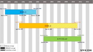
Data can be downloaded here.
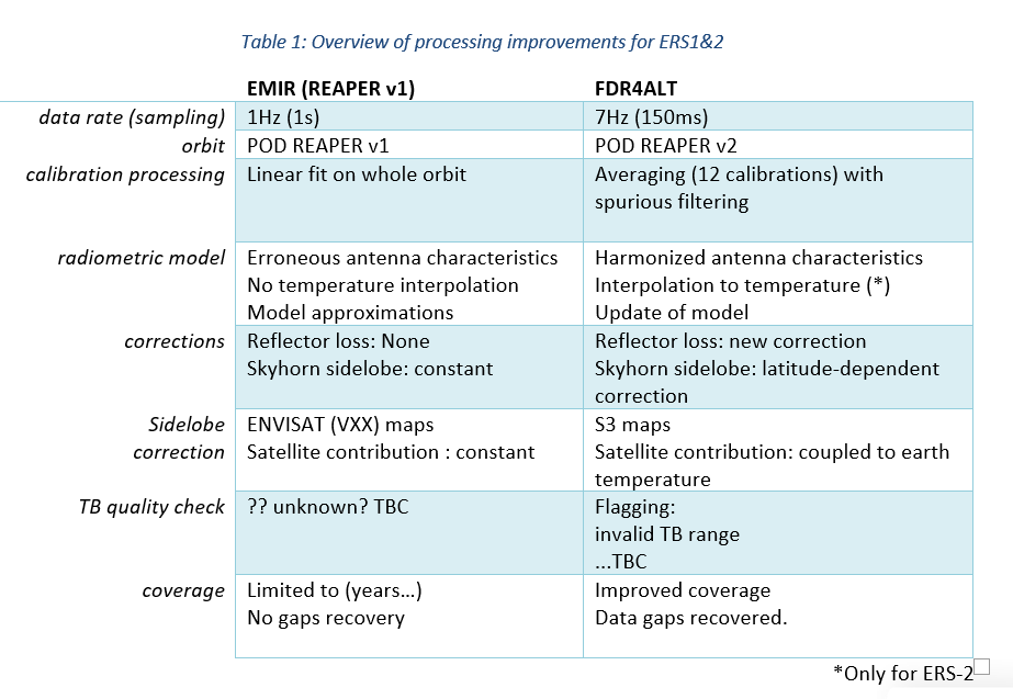
Improvements compared to existing products
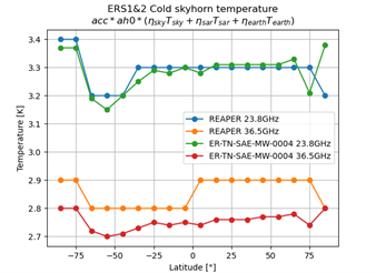
Skyhorn sidelobe correction (ERS)
The sky horn receives contributions sky but also from the earth and from the SAR antenna within this solid angle (aperture of 40°).
In REAPER reprocessing, the cold sky temperature as seen by the skyhorn is provided tabulated by 10° bins of latitude.Some inconsistencies were found in the REAPER reprocessing.
In FDR4ALT reprocessing, we chose to use the Tcold table used for REAPER. It was divided by ERS-1 acc/ah0 coefficients to retrieve the original table, and the prototype was updated to perform the multiplication inside the code according to each mission characterization file.
Reflector loss correction (ERS)
For both ERS missions, the physical temperature of the reflector (Tp) us not measured, hence the reflector loss is not considered in the radiometric model. This correction can impact of 3 to 6K the antenna temperature retrieval, depending on the value of reflector transmission (nref) chosen.
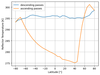
To provide a table of Tp temperature, one day of S3A reflector temperatures was separated by ascending and descending passes, averaged by 5° bins of latitude than and scaled to be within the 288+-13K temperature range of ERS (ref doc). The reflector loss correction is then applied on TA by selecting the appropriate Tp corresponding to the measurements latitude.
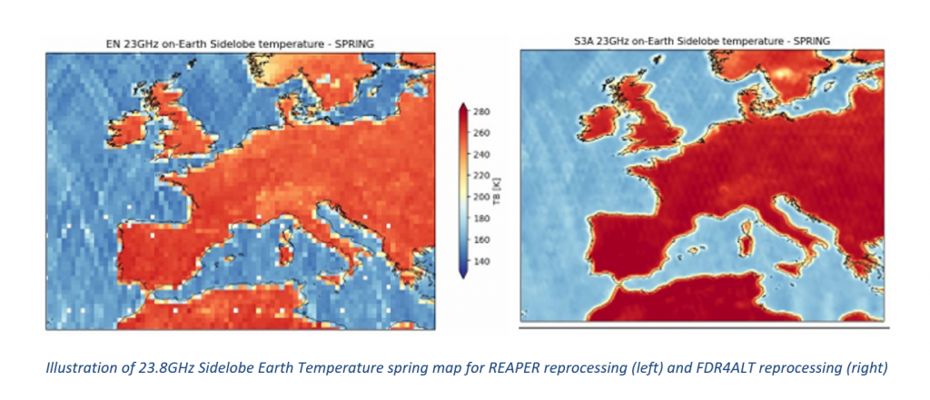
Sidelobe correction (ERS)
The sidelobe correction is used to compute TB from antenna temperature. It can be written as a combination of contributors emitting in the antenna field of view. A portion of the antenna measurement is contaminated by cold sky, satellite, SAR antenna emission as well as earth emission in the side-lobes.
Considering that
- Only a contour plot of ERS-1 antenna pattern was available and no information was found about ERS-2 one.
- ENVISAT antenna pattern used for previous reprocessing is very different from ERS one and shows larger sidelobes.
- The digitized antenna patterns of ERS-1 and measured sentinel3A were found to be quite similar
The Sentinel-3A antenna pattern was chosen to be used in the FDR4ALT project. The earth sidelobe correction can be computed directly from S3A sidelobe correction maps: a set of seasonal high-resolution grids (0.2°) of TB of S3A convolved with the 4pi antenna pattern of S3A. The enhanced grid resolution will allow to improve the data quality in coastal areas.